Environment Aware Smart Car
Aim of this project was to develop the hardware and the software for a self-navigating smart car. The car would employ the use of multiple sensory devices to determine changes in the surrounding environment and adapt to these changes. It would choose an efficient path from starting to stopping points based on a justified criterion. This involved developing an algorithm to be implemented on a microcontroller
controlled vehicle and integrating multiple modules and circuit devices together to achieve that common goal. Finally, the car would be able to share knowledge gathered about the environment to third party entities.
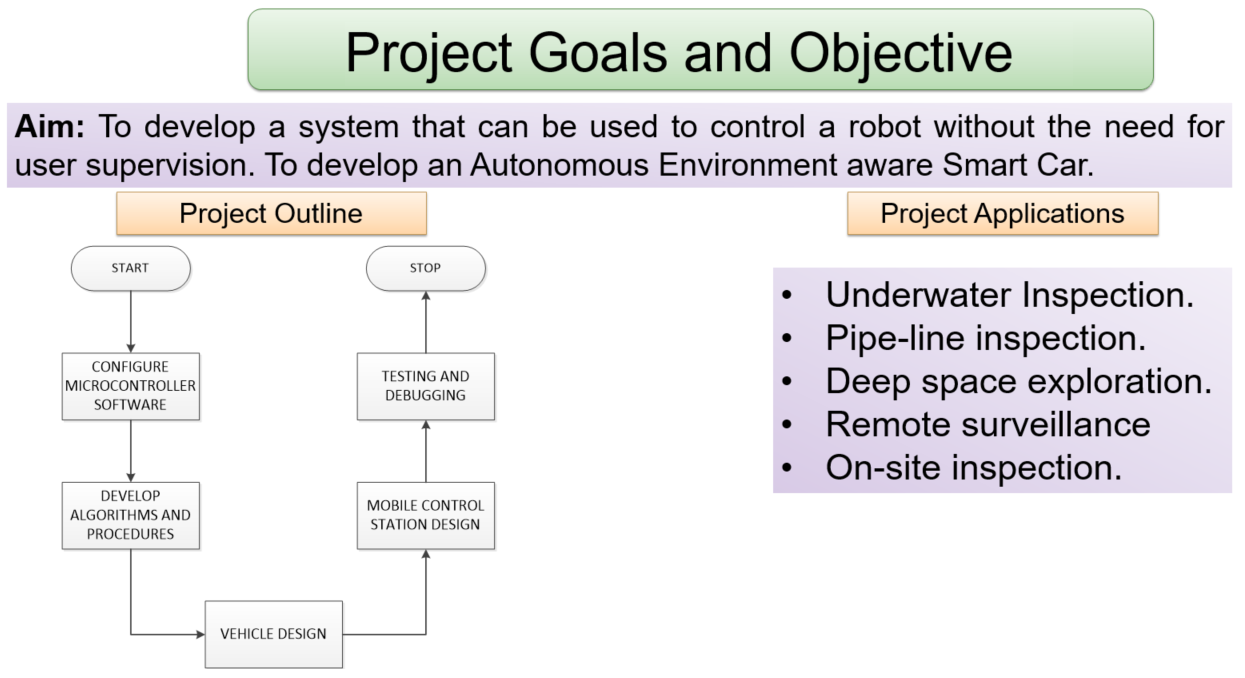
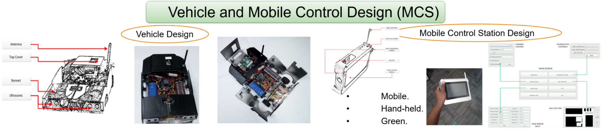
The project began with the design and construction of the vehicle. This included constructing the vehicle chassis, selecting and incorporating multiple individual components and configuring the components to work together. The components were chosen based on the functional requirements of the of the project. The base functions of the smart car were also programed in the stage of the project. After the basic functionality of the vehicle was achieved, the more complex algorithms were developed and incorporated into the vehicle operating system. The vehicle was then dry tested.
Hardware and Software Design of the Project
Choice of Microcontroller. The project required a high speed microcontroller that is fast enough to handle the processing requirements without delaying the vehicle operation. A suitable operation frequency is more than 100MHz. The microcontroller must have enough Random Access Memory (RAM) to be able to process images of a large size. Multiple copies of the images will be databased in the microcontroller’s memory to provide the vehicle with a memory component. Also the microcontroller memory must also hold multiple code variations within its memory. The RAM size must, hence, be greater than 50MB. The microcontroller will need to operate motors, drivers and communicate with other modules and hence it should have enough external pins to meet that input and output requirements of the
vehicle. The controller must be capable of multiple methods of wired communication including serial, i2c bus and/or SPI. For this project, a
Raspberry Pi B+ microcontroller was chosen.
Choice of GPS Module. For the GPS module, the module must be able to perform a Hot Start and obtain a fix at low SNR to reduce power consumption. The module must also be able to use a GPS enhancer software to improve its accuracy. It must be accurate within 5m (The range of the obstacle detector) and must communicate with a wired serial at a changeable baud rate. The format of the information
the module sends to the microcontroller must be in the National Marine Electronics Association (NMEA) standard. The module must be low voltage and give a high speed response. It must have an external ceramic antenna to improve signal reception. The module must be able to keep fix while in motion hence should have a high speed tolerance. With the above requirements in mind, the chosen module was the U-BLOX VKEL VK16U6 module.
Choice of compass module. Most compass modules on the market perform similar functions. They have similar capabilities only being distinguish by their rate of response and accuracy. For this project, there are no special requirements needed with regard to the compass module. Any module that does the job is acceptable. The chosen module was the HMC5883L Magnetometer module which is cheap, readily available and relatively easy to work with.
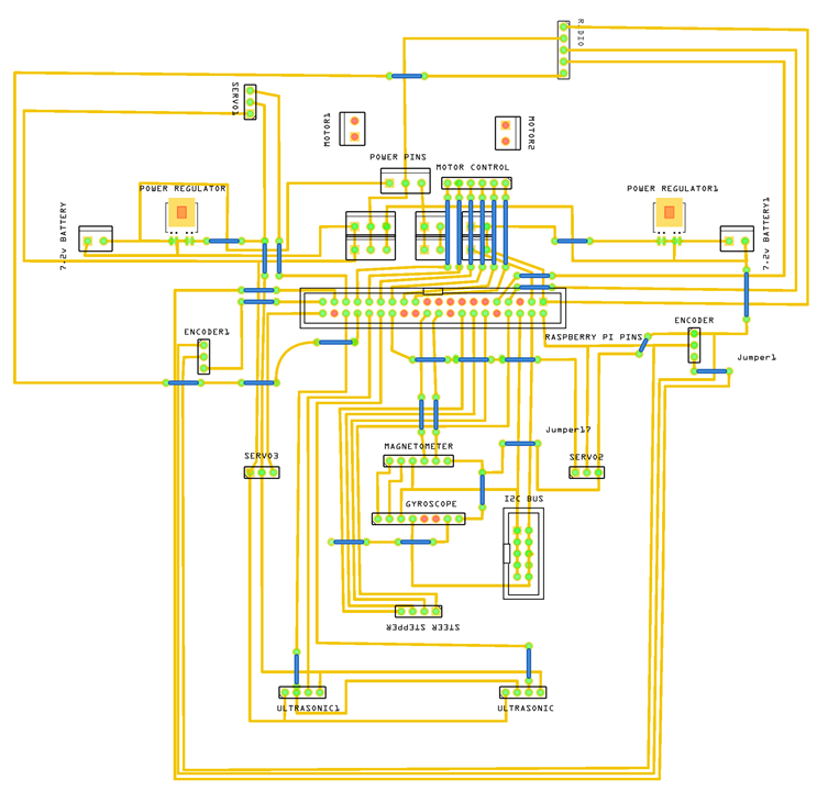
One other important aspect of the vehicle design is the care that needs to be taken in the design of the circuit map of the vehicle. The wires must not be too long to introduce an unwanted resistive component that will affect the vehicle’s operation and sensor readings. The wires must not be so close as to introduce a capacitive component that will in turn introduce high harmonic frequency components. This will affect the readings of magnetic reliant sensors. The circuit map shows how all the individual components were linked together. This includes the main components discussed above and some minor components that were necessary to realize the full functionality of the vehicle. These include:
- Ultrasonic Sensors
- Infrared Wheel Encoders
- Radio Transceiver modules - Brushless motors and stepper motors - Voltage regulators
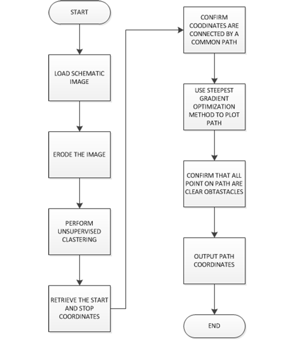
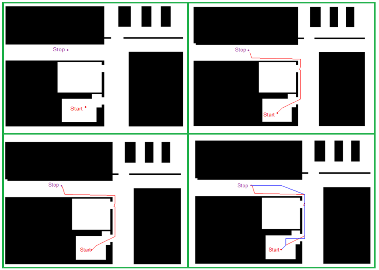
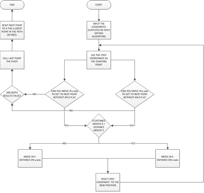
The first part of the navigation algorithm is a path defining algorithm. This algorithm defines a path between 2 given point. The algorithm requires an image floor plan to be loading in the program and then the algorithm uses this image to define a path between the two points avoiding obstacles on the path. The algorithm first checks if the two points are connected by a common path. The function will not run if the two points do not share a common path. The loaded image is a gray scale image (or is turned to gray scale if it was not when it is loaded) with values ranging from 0 to 255.
Once the program loads the image, the first stage of the algorithm is to erode and dilate the image in order to fill in gaps in the image. After this, the algorithm runs a filter kernel through the image that will set each pixel in the image into a set of values greater than 200 or less than 45. This allows the definition of a threshold between 200 and 45. All values greater than the threshold are set to 255 and all the values less than the threshold are eroded to zero. The image is now literally black and white. The next stage, the algorithm runs the connected components algorithm. At the end of this algorithm the image will be segmented and each segment will be labeled with a value. It is after this stage that the algorithm checks if the points are connected. If they are, the labels on their image positions will be same, else that algorithm will display an error massage and halt. The algorithm uses the gradient between the 2 points to determine the direction to move from one point to the other. Using this direction, a small step size to move is defined. The algorithm will move only one small step at a time. It will define a proximity limit by which only the path is within the proximity. 42 If the proximity limit is violated, then the then a new step is found. This new step has to be such that it can converge to the goal or stopping point, it does not violate the proximity limit and is on the same path as the starting and stopping points. After the program moves to this new point that is one step size from the starting point, the program updates the new point as the new starting point and places the direction and pixel distance moved into a matrix that defines the path from starting point. The algorithm will iterate
the procedure above until it gets to the stopping point.
The issue with this algorithm is that it is too precise. It defines multiple turns at significant detail that it does not account of the physical limitations of the vehicle to follow the path that it defines. The vehicle has small fluctuating error in distance moved and angles turned. These error are random non-deterministic. This means that it would take much more complex statistical evaluation algorithms to predict and account for the possible errors.
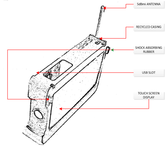
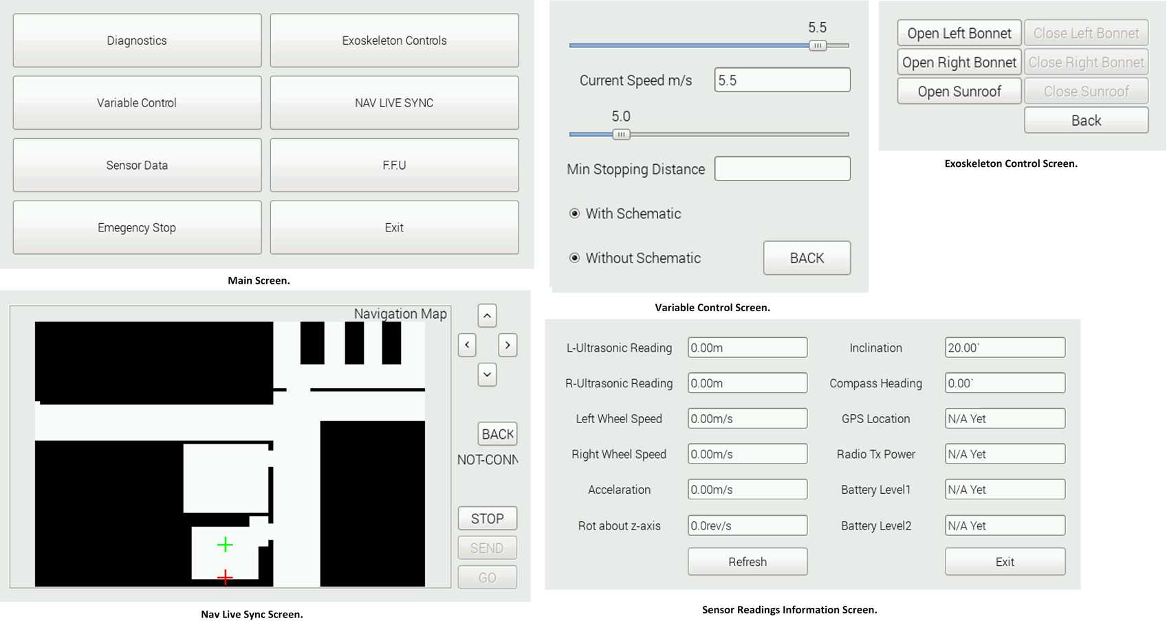
The vehicle comes with a Mobile Control Station (MCS). The main purpose of the MCS is to transfer information from the vehicle to the operator. This information includes the run status of the vehicle, readings from the sensors on the vehicle, the task current being performed, movement of the vehicle and status of the vehicle’s individual components. Another purpose of the MCS is to give the
operator a certain measure of control over the vehicle. From the MCS, the operator can adjust variable limits for example speed and breaking distance, instruct the vehicle to move to a specified location, monitor the movement of the vehicle, monitor sensor readings, control the vehicle covers, shut the vehicle down. The MCS is mobile. This allows the operator to control the vehicle while seeing how it moves if they want. The MCS would communicate wirelessly with the vehicle, that way the operator can obtain real-time data from the vehicle.
The MCS also uses a RTOS made up of three tasks. The first is the main task that is responsible for the operation of the GUI at the MCS. The second and the third are communication tasks that operate in the same manner as the tasks task6 and task7 at the vehicle side. In fact, in order to maintain the uniformity of the communication between the vehicle and the MCS, the 2 communication tasks at the MCS are exact replicas of task6 and task7 at the vehicle side.
As the technology advances on a global scale, most of the old installations are migrating to intelligent automated systems. This phenomenon is being seen in every industry ranging from automation to consumer product development. These automated systems that work faster and more efficiently have led to an increase in production size. We have bigger machinery in bigger factories. This also
means that there is a larger risk to human life in the event of catastrophic failures. Inspectors need to walk longer distances to make sure that everything is working as it should and this places a stressful burden on their bodies leading to possible fatal mistakes being made. Other areas of these bigger plants and factories have been automated to the extent that they are no longer easily accessible and no one would have a clue if everything there is working as it should or not. Hence, industrials are adopting the ignorant perspective
that as long as the machine is working, everything is fine. Situation like these require an autonomous surveillance system that will allow the operator to see place they cannot access remotely and make an informed diagnostic of the system that will not put lives at risk.
Apart from the above scenario, deep ocean and deep space exploration teams require such technology to collect analyze sample and report back information. All these possible scenarios motivated this project. The main goal of this project was to develop an autonomous vehicle that can travel from a designated start point to a stop point while deciding of which effective path to take to achieve its goal and achieving this goal without user intervention. The vehicle would also have to report information back to the user/operator about its environment.
The project began with a review of the multitude of literature that focused on robot navigation in known and unknown environments as well as communication literature to help in design a communication standard for the vehicle. Using all the information obtained from the literature review, a navigation algorithm was designed at debugged and a Mobile Control Station was designed that will facilitate the communication between the operator and the vehicle, giving the operator a measure control over the vehicles operation. This Mobile Control Station was built and tested. A communication protocol was also developed that will allow the vehicle to communicate only to the mobile station. Finally, the full system was tested to see the extent at which the goals of the project were met.
The result of the project is the Environmentally Aware Smart Car. The vehicle still has room for improvement, as discussed above, to produce a better mode reliable product. At the end of the day, the goal is to make life easier through the creation and development of advance technologies.